

Controlling LED strips with DMX512 relies on a three-tier architecture: "Control Console → Decoder → LED Strip." The key lies in correct wiring, assigning DMX addresses, and matching the number of channels; finally, adjusting the faders on the control console will activate the lights. You can also use dimming functions by pairing software such as Madrix, LED Build, or LED Studio with compatible LED controllers. Below, we’ll walk you through the process step by step, covering principles, equipment, wiring, address configuration, console operation, and common issues. Relevant LED controllers will also be further explained in the following descriptions.
I. Understanding the Principles
> DMX512 is a digital lighting control protocol. A single link supports up to 512 channels, where 1 channel = 1 dimming value (0–255).
>Standard RGB light strips: 3 channels per meter (R=1, G=2, B=3); RGBW: 4 channels per meter.
Signals are connected in series (daisy-chain), while power is connected in parallel. A 120Ω terminating resistor is
required at the end of each link—whether it’s the last fixture or a DMX-LED decoder—to prevent signal reflection.
II. List of Essential Equipment
1. DMX512 console / DMX LED controller
Stage: Basic 24-channel → Professional GrandMA2/3
Small-scale: Artnet-DMX LED controller (with computer software such as Madrix, LED Studio, etc.)
DMX ConsoleDMX artnet Controller 4/12/20/30 universe
2. DMX512 Decoder (Required)
>Function: Converts DMX signals into PWM signals that the light strip can recognize
>If using standard PWM constant-voltage LED light strips, connect them to a DMX512 decoder.
>Specifications: RGB = 3 channels, RGBW = 4 channels; Voltage: 12V/24V (same the light strip)
>For standard PWM constant-voltage light strips, the maximum length of LED strip that can be connected to a single decoder depends on the decoder’s load capacity.
>If you want to control SPI LED strips via DMX, you must connect an SPI DMX LED decoder. Generally, a single SPI DMX LED decoder can support up to 512 addresses.
If the SPI LED strip has 60 RGB LEDs per meter and 20 pixels, meaning one meter occupies 60 addresses, then a single decoder can support 8.5 meters of such a strip.
>If using a DMX pixel strip, there is no need to connect a DMX 512 decoder. DMX pixel strips can be connected directly to a DMX console or a DMX LED controller.
LED Strip connection with mini DMX Decoder ( Waterproof)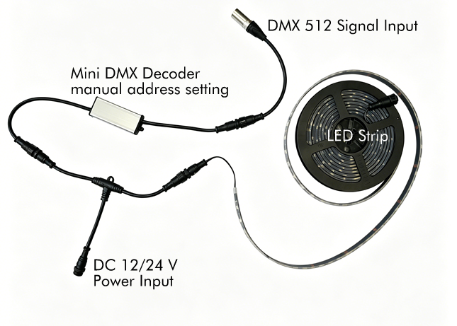
3. DMX512 LED Strip Lights
DMX pixel strips typically feature 10, 16, or 20 pixels per meter, depending on the model. (The strip’s PCB contains a DMX IC, such as the TM1803 or SM18512.) Common configurations include 4-wire (V+, GND, DAT, PI) or 5-wire (V+, GND, A, B, PI) setups.
4. Power Supply
Voltage: Same as the LED strip (12V/24V)
Power: 1.2–1.5 times the total power of the LED strip (allow for a margin)
5. Cables
Signal: ** Shielded twisted-pair cable (DMX cable) ** or Cat5e/6 (A=D+, B=D-, Shield = GND)
Power: 2-core multi-strand copper wire (select wire gauge based on current)
III. Wiring Procedure
The following describes how to connect standard PWM constant-voltage LED strips to a DMX controller.
1) System Topology (Signal in Series, Power in Parallel)
DMX Console (DMX Out) → Decoder 1 (DMX In → Out) → Decoder 2 → … → Last Decoder (with 120Ω terminating resistor)
2) Decoder ↔ LED Strip (using a 5-wire RGBW strip as an example)
Decoder: V+, GND, R, G, B, W
LED Strip: V+, GND, A (D+), B (D-), PI (PI is generally not connected)
Wiring: V+ → V+, GND → GND, R → A, G → B, B/W left open (As defined by the LED strip IC)
3) Power Connection Method (to Avoid Voltage Drop)
The decoder and LED strip share the same power supply; positive and negative terminals must match.
Long distances (>5 meters): Recharge every 5–10 meters to prevent the front end from being bright while the rear end is dim.
Connection methods for DMX LED strips or SPI LED strips are as follows.
1) Computer (or controller supporting SD card reading) → LED strip
2) Power Connection (to avoid voltage drop)
Add a power source every 5 meters for 12V strips, and every 10 meters for 24V strips
IV. Setting the DMX Address (Critical!)
Each section of LED strip or decoder must have a unique starting address to avoid conflicts.
RGB: Uses 3 channels (e.g., starting from 1 → 1/2/3)
RGBW: Uses 4 channels (e.g., starting from 1 → 1/2/3/4)
1) Setting the DMX Address (Two Methods)
Decoder DIP Switches: Set the address in binary (1–512)
DMX Programmer LED Display Buttons: Press SET → Adjust the address → Save (Common)
DMX Address Writer (Digital Type)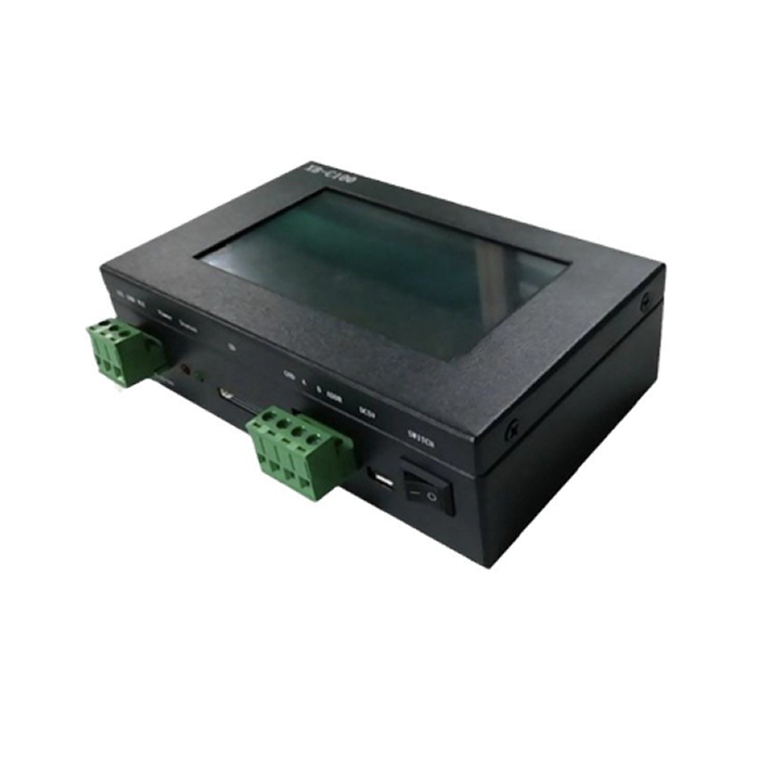
2) Address Assignment Example (3 RGB Light Strips)
Light Strip 1: Start Address 1 → Channel 1 (R), 2 (G), 3 (B)
Light Strip 2: Start Address 4 → Channel 4 (R), 5 (G), 6 (B)
Strip 3: Start Address 7 → Channels 7 (R), 8 (G), 9 (B)
For SPI LED strips or DMX LED pixel strips, each pixel occupies 3 addresses for an RGB pixel and 4 addresses for an RGBW pixel.
V. Console / Software Operation (Quick Lighting Setup)
1) Hardware Console (using a 24-channel console as an example)
1. Power on the console, decoder, and light strips.
2. Set the start addresses for each light strip as described above.
3. Faders 1 (R), 2 (G), and 3 (B) → adjust color; Fader 0 → blackout, 255 → full brightness
4. Create scenes: Save color/brightness combinations for one-click recall
2) Computer Software (Artnet-DMX, suitable for large, medium, and small projects)
>Software: Madrix, Resolume, QLC+ (free)
>Steps:
1. Connect Artnet-DMX to the computer and set the IP address
2. In the software, select the DMX interface and configure the address and channels
3. Create effects (fades, parades, chases) or trigger them with music
VI. Common Issues and Troubleshooting
1.1, LED Strip Does Not Light Up
>Power supply polarity reversed; voltage mismatch (connecting a 12V LED strip to 24V will cause it to burn out)
> Incorrect DMX address; signal lines A/B reversed
2.2, Flickering / Flickering
> No 120Ω terminating resistor installed on the last unit
> Signal cables are unshielded or run parallel to high-voltage power lines
3.3, Uneven Brightness
Cable run is too long without a power booster; power supply is insufficient
4.4, Control Console Unresponsive
>DMX chain exceeds 32 units or 300 meters; a signal amplifier is required
VII. Simplified Setup Procedure (Light Up in 5 Minutes)
1. Equipment: 24-channel controller + 3-channel DMX decoder + 5-meter 24V RGB DMX light strip + 24V power supply
2. Wiring: Controller DMX Out → Decoder DMX In; Decoder V+/GND → Power supply; Decoder R/G/B → Strip A/B/GND; finally, install a 120Ω resistor on the decoder
3. Set Address: Set the decoder’s start address to 1
4. Power On: Power on the power supply first, then the console
5. Move console faders 1/2/3 to adjust colors—done!
Ⅷ, If you do not use the DMX console, you can choose the LED controllers. These controllers come pre-programmed with effects, or you can use compatible software on a computer or mobile device to edit LED lighting effects. The edited effects can then be sent to the LED controller via SD card, Ethernet cable, or Bluetooth. ISEELED offers DMX PWM decoders, including the LED-D4PWM, LED-D6PWM, the LED-D24PWM and SPI DMX LED decoders. The SPI DMX decoder support the WS2801, WS2811 series, UCS series, and various other standard SPI protocol chips. SPI DMX decoders are compact and often feature waterproof enclosures, making them suitable for a wide range of applications.
For DMX controllers, we primarily recommend SD card-based master/slave controllers, and DMX ArtNet controllers such as the LED-ANC-4X512, LED-ANC-12X512, and LED-ANC-20X512. and model LED-ANC-4X512-PSU